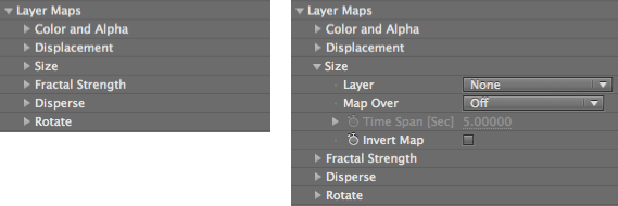
Layer Maps group
The Layer Maps group enables the pixels of another layer to control various aspects of the particles in the grid. Most Layer Map groups work with the luminance values of grayscale maps, which treat black pixels as 'off', white pixels as 'on', and gray pixels as transitional values. This page covers the common parameters, along with six subgroups that specify the source layer and what kind of layer map is used.
Color and Alpha group
Displacement group
Size group
Fractal Strength group
Disperse group
Rotate group
The Layer Maps group and a subgroup exposed.
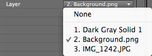
Layer pop-up
All Layer Maps have a Layer menu, which lets you specify a source from an existing layer in your Timeline. If you specify a source layer that contains no animation, Form will generate a static grid. If the source layer changes from frame to frame, Form will use this information to generate an animated grid.
NOTE: Any layer used as a map must be pre-composed or pre-rendered to be used as a source for Form. In general, the best results are when the size of the layer map equals the size of the particle grid as defined in the Base Form controls.
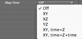
Map Over pop-up
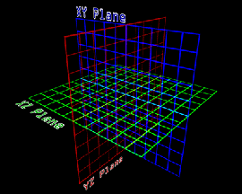
All Layer Maps have a Map Over menu. To get the right result for mapping, make sure that the Map Over plane has the appropriate particles to render an image. For example, if you are mapping over the XZ plane, make sure to have a grid of particles specified for this plane by setting the Particle group> Particles in X and Particle in Z to values of 30 or more.
![]()


Left to right, the layer map; mapped over XY Plane with 300 x 300 particles; mapped over XZ Plane; mapped over XY Plane.
Time Span [Sec]
Controls the point at which the animation will affect the planes in Z space. This control is active for the Map Over options of XY Time=Z and XY Time=Z+Time.
Invert Map checkbox
All Layer Maps have an Invert Map checkbox. This feature saves you from having to create precomps of the same map, only inverted, in order to get the same effect.
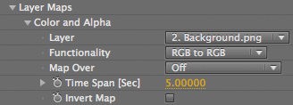
Color and Alpha group
The Color and Alpha group lets you use a layer to control the particle grid with the color and alpha channels. The colors are used for each particle from the RGB channels. The alpha channel defines transparency, making the particles 100% transparent where the alpha channel in the layer is black.
![]()
At left, a precomp of a shape layer star. In middle, the form grid.
At right, the precomp is the Color map, with Functionality at RGB to RGB, and Map Over at XY.
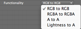
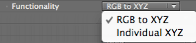
Color and Alpha> Functionality pop-up
Sets how the particles interact with the layer map's color and alpha properties.
Displacement group
The Displacement group lets you displace particles in the form using the luminance values of a source layer.
A neutral gray (128, 128, 128 in 8-bit RGB) means no displacement. Colors that are darker than neutral gray will generate negative displacement, and will be pushed farther away from the viewer on the Z axis. Lighter colors result in positive displacement and will be pushed closer to the viewer.
![]()
![]()
At left, a precomp of fractal noise. In middle, the form grid.
At right, the precomp is the Displace map, with Functionality at RGB to XYZ, Map Over at XY, and Strength at 30.
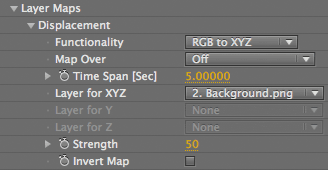
Displacement> Functionality pop-up
Sets how the particles interact with the Separate color channels of a layer map. This pop-up lets you assign an individual map for X, Y, and Z.
Displacement> Layer for X, Y, Z pop-ups
Sets the Layer Map for the planes that are identified. These controls are enabled by the Functionality menu.
Layer for XYZ: A single pop-up that sets the Displacement Layer Map to the X, Y and Z planes. This pop-up is enabled by the RGB to XYZ option.
Layer for X, Layer for Y, Layer for Z: Three pop-ups that set the Displacement Layer Map to the X, Y and Z planes. Enabled by the Individual XYZ option.
Displacement> Strength
Controls the strength of the displacement. At value of 0, there is no effect. As you move into positive values, the displacement becomes more extreme. In negative values, the displacement will recede into the original base form and will eventually move in the opposite direction.
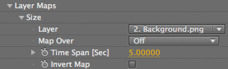
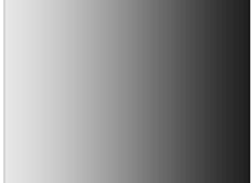
Size group
The Size group lets you change the size of the particles in the form by using the luminance values of a source layer. Black regions of the layer image will have a particle size of 0, which creates holes in the form. White regions have their particle size set to the maximum value of the Particle group> Size control.
![]()
![]()

At left, a precomp with a gradient linear wipe. In middle, the form grid. At right, the precomp is the Size map, with Particle Size at 2.
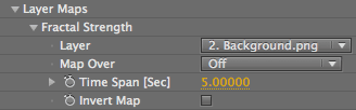
Fractal Strength group
The Fractal Strength group lets you specify a layer whose luminance values define the extent to which any fractal information is used to deform or perturb the form. Areas that are light in color (or luminance) will be affected by the the Fractal Strength settings, while darker parts will be less affected. Black parts will not be affected at all.
The amount of dispersion is set in the Fractal Field group. If the Fractal Field> Displace control is set to 0, then no deformation will occur. Once Displace has a value, you will see the layer map pushing pixels around, and you can use the other Fractal Field controls to affect the map.

![]()
At left, a logo layer. At right, Fractal Strength with a high Displacement and the Octave Multiplier and Scale at 2.0.

![]()

At right, a precomp with a feathered mask. At right, using the precomp as the Fractal Strength map.
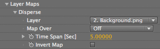
Disperse group
The Disperse group uses a layer map to create particle dispersion in the form, similar to how the Fractal Strength group works.
The amount of dispersion is set in the Disperse & Twist group. If the Disperse & Twist> Disperse control is set to 0, then no dispersion will occur. Once Disperse has a value, you will see the layer map pushing pixels around.
![]()

At left, a logo layer. At right, using the layer as a Disperse map.
![]()
![]()
At left, a precomp with a gradient linear wipe. In middle, the form grid. At right, the precomp is the Disperse map, with Disperse at 25.
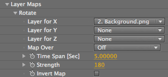
Rotate group
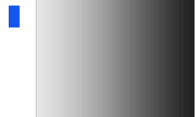
The Rotation Group lets you specify a source layer whose luminance values define the extent to which the particles will rotate. Areas that are light in color (or luminance) will be affected by the Rotation, while darker parts will be less affected. Black parts will not be affected by all. White parts, by default, will rotate 180 degrees.
![]()
At left, a blue box loaded as the custom particle, and a precomp with a gradient linear wipe.
At right, Layer Y and Layer Z have the linear wipe loaded, and Map To is XZ.
Rotate> Layer for X, Layer for Y, Layer for Z
Sets the layer map for the planes that are identified. Layer for Y sets the source to the Y plane, and so on.
Rotate> Strength
Controls how much the particle will rotate when presented with a white value in your luminance map. By default, Strength set to 180, which means that when you have a white value, that particle will have rotated 180 degrees.